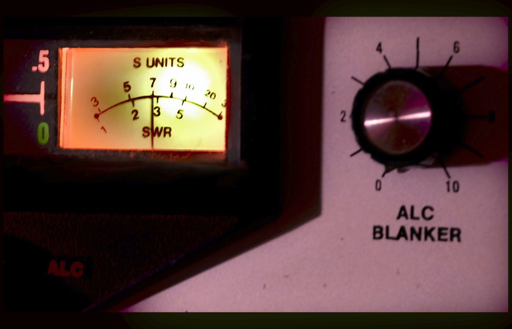
Figure 1: The old S meter on the Triton 4 is registering signals above zero again.
The Triton IV is a radio I’ve had close to my inner ham’s happy thoughts for a long while. It’s antiquated by today’s standards, having been manufactured first in 1976. It’s almost 100 percent analog, unless you count a few old gate chips on the control and calibrator boards. Its 70s era-styled case is infamous for being the flimsiest ham radio chassis enclosure ever built. For this reason, it has always been advisable to place it on a stout table, keeping the brass pounding and attendant vibration damped down to a suitably less energetic level. But, the receiver is pretty sharp, has no hiss or phase noise, and the sensitivity has always managed to be plenty enough for my rag chewing QSOs.
It’s that sensitivity that plummeted one day, while I was working twenty meters. Suddenly, I could hear the other station barely. More alarmingly, the noise had also disappeared. It was as if the antenna disconnected, and I was picking up the little bit of signal that could penetrate the circuits directly through the case. To check this, I sent out a signal and watched the SWR, letting the other ham know I was going to have to QRT. The transmitter was OK, and the SWR was perfect. That mean’t that … Oh Oh.
Note: Quite a while ago, I had anticipated an eventual “Oh No!” moment. Accordingly, I located a half dozen or so NOS 40823 MOSFETs for the junk drawer. So, the dread that might normally accompany the last paragraph was diminished somewhat. HiHi.
It immediately dawned on me that the RF amp’s MOSFET input (front end) transistor had given up the ghost. So, I took the Triton apart to do a replacement, feeling that was something I most certainly would have to do. Checking the voltage on the calibrator wire coming out of the preselector partition seemed to show that gate #2 on the MOSFET was operating correctly. The drain, source and first gate terminals of the MOSFET still needed to be checked. This was no easy chore.
I am one to compliment Ten Tec on almost every aspect of their builds, but the preselector stack on the Triton is definitely a PITA. The resonator knob is attached to an elevating core assembly that moves the ferrite cores of L1 and L2 up and down on the RF amp board. This is a bit nifty, as an idea. It works well. But, the RF board is nested below the elevator assembly, and is screwed into the chassis from the other side of the board. So, you have to pull the board out from the bottom AFAIK. I suppose you might work a screwdriver in between the partition walls somehow, to loosen the screws, and then take it out from above. Before any of that can happen, you have to desolder about a dozen wires and component leads. This was a long, messy job just to get a couple measurements on the MOSFET.
Run across a dental pic or a dental mirror at a flea market? Buy it!
So, I put my tiny dental mirror to work, hoping that with the mirror, I could successfully land a probe onto the PC board foil for the other gate, the drain, and source, without blowing anything up. BTW, if you ever run across a dental mirror at a flea market or antique store, definitely buy it! It was worth the $5 already, and I got a nice pic along with it.
Well, getting the flashlight to line up with the mirror while working the probes was seriously challenging for an old guy with only two hands. I don’t think I landed the probe properly, but in the process of pushing and pulling things, I miraculously solved the problem. Suddenly, the S meter popped up to 20 db over nine. W1AW/4 was calling “CQ contest”. What a beautiful signal that was to hear! Of course, this meant that I had a cold solder joint. After forty seven years of life it for some reason decided to lift its head. It just goes to show ya! Sometimes it’s easier than it looks.
In retrospect, it might be that the resonator knob and attendant elevator assembly put a little mechanical push or pull on the RF board as it “elevated” or “de-elevated” – and this eventually pushed the cold solder joint open. Or not. So, I made sure that the cores were centered in the shafts, so that further mechanical stress could not happen, and heated some of the terminals. Don’t know if I heated the right one(s), but at least I know where to look if the problem ever returns.